- Mixed assembly planning should be treated as a route-definition problem, not as a loose list of process buzzwords.
- The most useful boundary is to separate SMT placement, through-hole insertion, selective or hand-solder branches, and inspection or release staging.
- A board can have a correct BOM and still create avoidable NPI friction if the assembly route, insertion timing, or exception handling is not frozen clearly enough.
- Mixed assembly planning should explain what must be decided before first build rather than inventing universal pallet, clearance, throughput, or capability numbers.
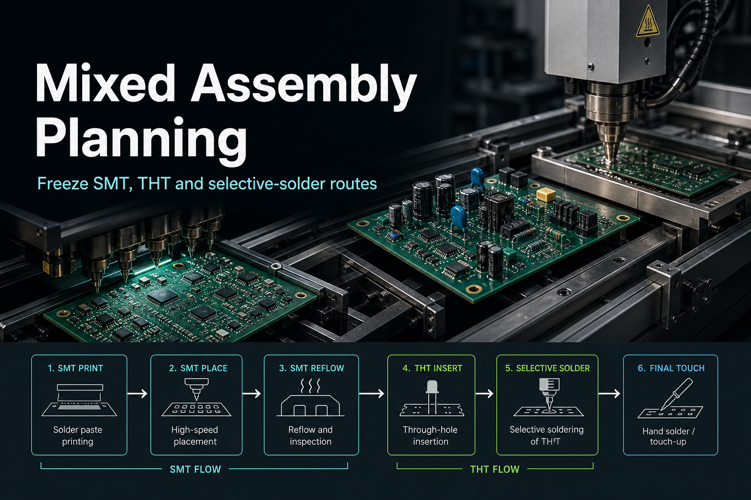
Quick Answer Mixed assembly planning is strongest when the team freezes the route in order: which parts belong to SMT, which parts are inserted later, which joints need selective or manual handling, and which inspection or electrical-test gates sit between those branches. Ask which assembly path each component family follows before the board can move into controlled verification and release.
For the broader stack that connects assembly input control, inspection, test planning, and release gates, start with the PCBA Assembly Test and Quality Guide.
Table of Contents
- What should engineers review first?
- What counts as mixed assembly planning here?
- Which route decisions create release risk fastest?
- How does mixed assembly planning connect to BOM, drawing, and verification?
- What should be frozen before RFQ, first build, or release?
- Next steps with APTPCB
- FAQ
- Public references
- Author and review information
What should engineers review first?
Start with population split, route order, special-process branches, and release ownership.
That order matters because mixed assembly planning is usually where a board stops being a generic layout and starts becoming a real build route.
The first engineering questions are usually:
- Which parts belong to the core SMT route and which do not?
- Which parts are inserted after reflow because they are through-hole, mechanically large, or process-sensitive?
- Which joints should be handled by selective solder, wave-oriented routing, or hand-solder exceptions?
- Which inspection or electrical-test stages must happen before the board moves to the next route branch?
- Is the released package clear enough that the factory does not need to infer the route on its own?
| Review boundary | What it answers | What it does not prove |
|---|---|---|
| Population split | Which component families belong to which route | That the full build package is already stable |
| Route order | When each assembly branch happens | That every quality gate is already closed |
| Special-process branch | Where selective or manual handling still exists | That one route is universally best |
| Release ownership | Which later gate still owns inspection, test, or first-build confirmation | That route planning alone releases the board |
What counts as mixed assembly planning here?
Here, mixed assembly planning means the board-level definition of how SMT, THT, selective solder, and hand-insert or hand-solder operations are staged before the build enters controlled verification and release.
That usually includes:
- separating SMT-populated content from through-hole content
- deciding when connectors, terminals, shields, or other inserted parts enter the route
- marking which areas need selective solder or other local treatment
- identifying which exceptions remain manual at this build stage
- aligning inspection and electrical-test checkpoints with the route order
- making sure BOM and drawing language describe the same route
It does not mean:
- one universal sequence for every board
- a promise about pallet geometry, cycle time, or throughput
- proof that every mixed board should use the same soldering branch
- proof that release is complete once the route exists on paper
That boundary matters because mixed assembly articles often drift into unsupported process-window or equipment-capability claims.
The safer rule is:
mixed assembly planning should explain route ownership and branch timing before it tries to explain production outcomes.
Which route decisions create release risk fastest?
The biggest problems usually appear where the component population and the chosen route stop matching each other cleanly.
1. SMT versus post-reflow insertion split
The route should make it obvious which parts belong to the main SMT flow and which parts wait until after that stage.
That matters most for:
- connectors
- terminals
- shields
- mechanically stressed interfaces
- large or awkward parts that do not belong in the same handling posture as standard SMT population
If the split stays vague, NPI teams start asking basic route questions too late.
2. Selective-solder versus hand-solder branch
Boards with localized through-hole content often need a clear decision about whether those joints fit:
- a selective solder branch
- another controlled local solder branch
- a manual exception path
The main goal is not to market one path as universally better. The main goal is to keep the release package from hiding the fact that different joints need different handling.
3. Mixed-process neighborhoods
When dense SMT and later-inserted THT content sit close together, route planning should expose the risk early instead of treating it as a shop-floor surprise.
The review should ask:
- does this area still support the intended branch cleanly?
- are there exception notes that should be visible in the assembly drawing?
- will later inspection or electrical verification depend on how this neighborhood is built?
One ugly failure chain appears when a compact mixed-assembly board places 0402 or even 0201 SMT parts less than a couple of millimeters away from the pins of a heavy through-hole power connector. On paper the neighborhood still looks routable. In selective solder, however, the process team is forced into a bad trade. A normal solder fountain at more than 260 C can wash out or thermally disturb the nearby small SMT parts. To protect them, the factory is pushed toward an aggressively shielded pallet or a very narrow nozzle window.
That thermal shielding solves one problem by creating another. Heat transfer into the through-hole joint is now restricted, capillary rise weakens, and barrel fill can fall well below an acceptable build condition. The connector pin may still show momentary continuity at factory test, but the joint enters the field as a high-resistance cold connection. Under real current load it heats, degrades, and can open catastrophically. Mixed assembly planning is therefore not a flowchart exercise. It is a physical compromise between SMT keep-out distance and the thermodynamics of selective solder.
4. Inspection and test timing
Mixed assembly planning is not only about solder route. It also affects when evidence can be trusted.
For example:
- visible SMT issues may need review before later insertion branches begin
- later through-hole or hand-solder operations may change what continuity or electrical screening should confirm next
- first-build documentation may need to reflect route exceptions before release moves forward
| Route decision | Why it matters | What can go wrong when it stays vague |
|---|---|---|
| SMT versus post-reflow split | Keeps the core route readable before build starts | The line inherits avoidable setup questions |
| Selective versus manual branch | Makes exception handling explicit | Different joints get treated as if they share one route |
| Mixed-process neighborhood | Exposes local route conflicts early | Inspection, insertion, or rework logic drifts late |
| Test and inspection timing | Keeps verification aligned with route order | Evidence is collected at the wrong stage or interpreted out of context |
A common mixed-assembly failure chain starts when the board leaves SMT, THT, selective, and manual branches only partly defined. A connector or shield is assumed to fit a later selective step, but the drawing and route notes do not make the split explicit. Setup then treats the neighborhood as if it shares one default branch, inspection happens at the wrong moment, and the first build discovers that insertion order, local heating, or rework access no longer matches the released plan. The downstream result is not just a documentation question. It is route confusion, late exception handling, rework, and release delay caused by one vague branch decision being repeated across the lot.
How does mixed assembly planning connect to BOM, drawing, and verification?
Mixed assembly planning only works when the route is supported by the rest of the release package.
| Package layer | What it mainly owns | Why it matters to mixed assembly |
|---|---|---|
| BOM | Component identity and population split | The route cannot be frozen if the part families are still ambiguous |
| Assembly drawing | Human-readable route notes, side context, and exceptions | Special handling has to be visible enough for setup and review |
| Inspection plan | Visible and hidden-joint review ownership | Mixed branches change when different inspection evidence becomes meaningful |
| Electrical-test plan | ICT, flying probe, continuity, or functional-test posture | The route changes when electrical verification should happen and what it is screening |
That is why mixed assembly planning should be treated as an alignment task, not as an isolated process note.
Useful companion pages:
- Assembly BOM Best Practices
- Assembly Drawing Essentials
- Design for Assembly Checklist
- Testing & Quality
- First Article Inspection
Related service paths:
What should be frozen before RFQ, first build, or release?
Before serious RFQ, first build, or release, freeze:
- the split between SMT, THT, selective, and manual branches
- the intended route order for each component family
- the exception notes that must appear in the assembly drawing or route package
- the inspection and electrical-test checkpoints that depend on route completion
- the alignment between BOM, drawing, and first-build expectations
If those items are still moving, the board may still be technically buildable, but the assembly route is not yet stable enough to behave like a controlled release package.
Next steps with APTPCB
If your high-density PCBA is already forcing SMT and THT content into the same tight neighborhood, if selective solder thermal shock threatens sensitive parts, or if you are not sure the pallet and nozzle strategy can still deliver real barrel fill, do not wait for pilot build yield to answer the question.
Send the Gerber or ODB++ package, BOM, assembly drawing, and your preliminary keep-out intent to sales@aptpcb.com, or start through the quote page. APTPCB's PCBA process and DFM engineering team will return a Mixed-Process Route & Soldering Clearance Review within 24 hours.
That review is built to catch the route conflicts before trial production money is burned: selective-solder clearance traps, pallet over-shielding, weak barrel-fill risk, and neighborhoods that look placement-clean in CAD but cannot survive the real thermal branch without yield compromise. The goal is to lock a route that does not force the factory to choose between washed-out SMT parts and underfilled through-hole joints.
If you need to go deeper first, review:
FAQ
Is mixed assembly planning only about using both SMT and through-hole parts?
No. It is also about when those parts enter the route, which branches stay localized, and which inspection or test stages must happen between them.
Does every mixed board need the same selective or manual process?
No. The route should follow the actual population and release posture of the board, not a generic rule copied from another program.
Why does the assembly drawing matter so much in mixed builds?
Because route exceptions and insertion timing often depend on notes that the BOM alone does not communicate clearly enough during setup and first build.
Can route planning be separated from verification planning?
Not safely. Mixed branches affect when visible inspection, electrical screening, and first-build confirmation become meaningful.
When is mixed assembly planning complete?
It is complete only when the population split, route order, exception notes, and verification checkpoints are stable enough that the factory does not need to infer the route from incomplete inputs.
Public references
IPC-7525C Table of Contents Public standards anchor for stencil-guideline and upstream print-control context.
IPC-A-610H Table of Contents Public standards anchor for assembly workmanship context.
IPC J-STD-001J Table of Contents Public standards anchor for soldered assembly requirements context.
PCBA Assembly Test and Quality Guide Companion page for the layered framing that connects assembly route planning to inspection, test, and release gates.
SMT & THT Assembly Support-page context for boards that combine surface-mount and through-hole assembly content.
Author and review information
- Author: APTPCB mixed-assembly planning content team
- Technical review: SMT, THT, and NPI route-planning team
- Last updated: 2026-05-13