- A continuity test checklist should be treated as an electrical screening and review layer, not as universal proof that the whole board is ready.
- The most useful boundary is to separate intended conductive paths, unintended isolation failures, electrical-access method, and release-stage ownership.
- A board can pass continuity review and still need AOI, X-ray, functional test, or first-article confirmation because those gates answer different questions.
- A continuity test checklist should explain what continuity screening can narrow before release and what still belongs to later inspection or powered validation.
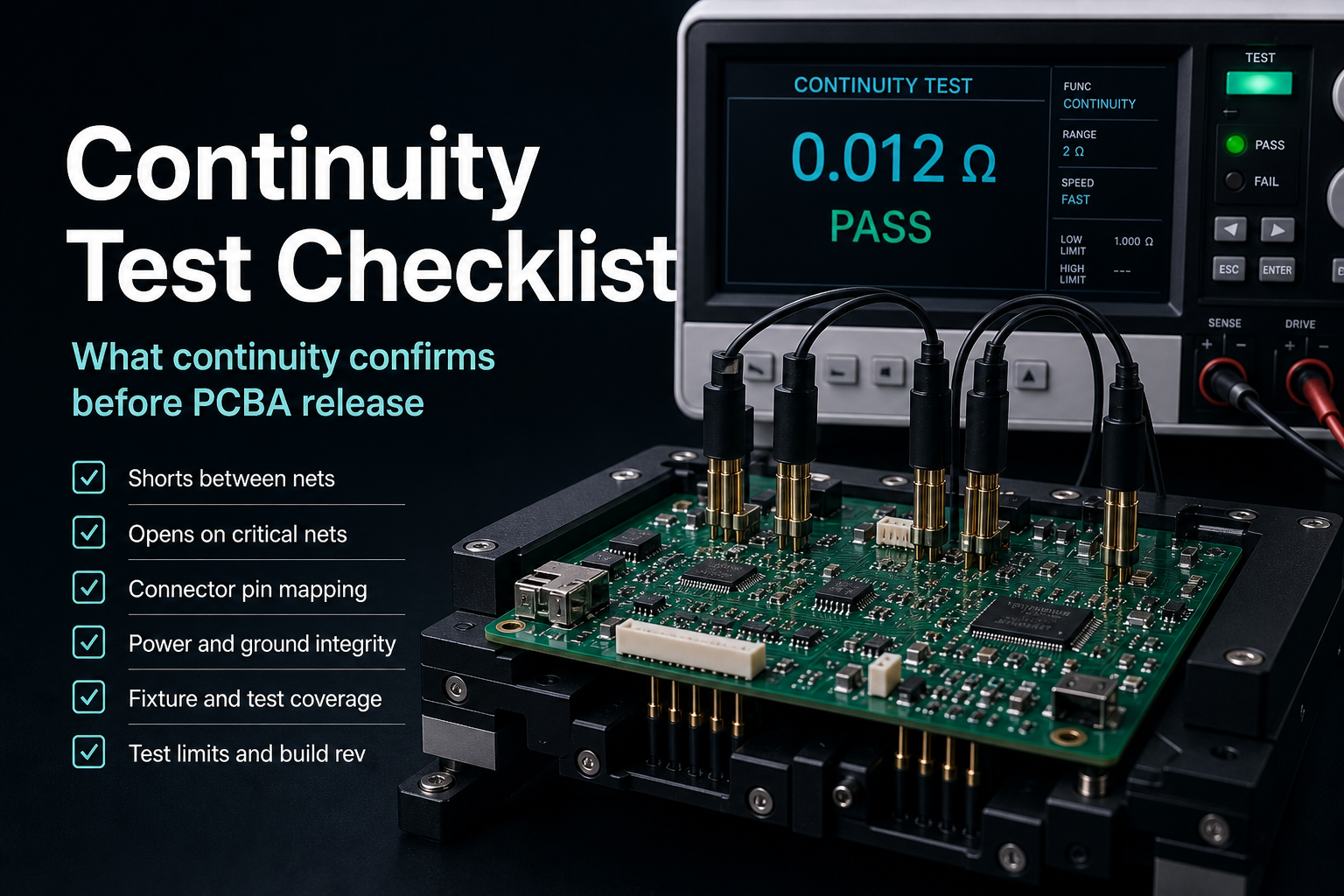
Quick Answer A continuity test checklist is strongest when it is used to confirm that intended paths are electrically connected, unintended bridges are not present, and the chosen access method still fits the board's release stage. It should be framed as one verification layer inside a larger PCBA quality path. Ask what defect risk continuity screening reduced and what evidence is still needed before release.
For the broader stack that connects inspection, electrical verification, and release gates, start with the PCBA Assembly Test and Quality Guide.
Table of Contents
- What should engineers review first?
- What counts as a continuity check here?
- Where does continuity review expose release risk fastest?
- How should continuity screening fit into verification and release staging?
- What should be frozen before continuity becomes a release gate?
- Next steps with APTPCB
- FAQ
- Public references
- Author and review information
What should engineers review first?
Start with test intent, electrical access, path criticality, and release-stage ownership.
That order matters because continuity test checklist is often described too broadly. In practice, continuity review is only useful when the team knows:
- which path is supposed to conduct
- which neighboring path must remain isolated
- which access method is being used to screen the board
- which later gate still owns visible defects, hidden joints, or powered behavior
The first engineering questions are usually:
- Is this continuity check being used for bare-board verification, assembled-board screening, debug confirmation, or release review?
- Does the board support fixture-based access, fixture-free access, or only limited manual review at this stage?
- Which nets, connectors, through-hole paths, or via transitions deserve explicit review because they sit on critical power or signal paths?
- What later gate still owns AOI, X-ray, FCT, or first-article evidence?
| Review boundary | What it answers | What it does not prove |
|---|---|---|
| Test intent | Why continuity is being run at this stage | That all later verification is unnecessary |
| Electrical access | How the board can actually be screened | Universal coverage or release readiness |
| Path criticality | Which connection paths deserve explicit attention | High-speed performance or powered behavior |
| Release-stage ownership | Which later gate still owns more evidence | That continuity alone closes shipment release |
What counts as a continuity check here?
Here, continuity test checklist means the review and screening layer used to confirm intended electrical paths and isolate unintended ones before release moves forward.
That can include:
- continuity of intended nets or connection paths
- isolation review between separate conductors
- connector and cable path verification
- through-hole or hand-solder path confirmation after assembly operations
- via-transition and return-path-sensitive review where the design already marks those areas as critical
- rework or first-build verification before the next release stage
It does not mean:
- proof of powered functional behavior
- proof of signal-integrity quality on high-speed channels
- proof of hidden-joint condition under concealed packages
- proof that one electrical check has qualified the full program
That boundary matters because continuity should not be exaggerated into a complete product-level verdict.
The safer rule is:
continuity screening reduces open, short, and path-interruption risk, but it remains only one layer in the release path.
Where does continuity review expose release risk fastest?
The highest value usually comes from the places where the physical build route and the electrical path can drift apart.
1. Connector and exposed-path review
Connector-near and externally exposed routing regions deserve explicit review because electrical continuity is not only about metal touching metal. The local return or reference path also needs to remain sensible when the board enters verification or release review.
Safe wording here is qualitative:
- preserve a local, continuous return context
- avoid treating split or interrupted reference regions as if continuity alone proves the path is healthy
- separate exposed routing zones from cleaner sensitive internal traces when reviewing risk
2. Via transitions and layer changes
When a signal changes layers, the electrical path does not stop being part of the continuity conversation.
The review should ask whether:
- the signal path stays electrically intact through the transition
- the local return context is still sensible after the layer change
- the design package has already flagged that transition as a risk area for later debug or release review
Continuity can help narrow open-path risk here, but it does not prove impedance or channel quality.
3. Mixed-assembly or hand-solder branches
Continuity review becomes more important when the board includes:
- through-hole insertion after reflow
- selective solder branches
- hand-insert or hand-solder exceptions
- connector or terminal operations added late in the route
Those branches create real opportunities for path interruption, wrong insertion, or partial connection. Continuity is useful there, but it should stay paired with route-aware inspection and release notes.
4. Documentation and staging drift
Continuity findings become hard to interpret when the release package is unstable.
If the BOM, assembly drawing, route notes, or test intent are still moving, a pass or fail can be ambiguous because the team may no longer be screening the board against one stable definition.
| Risk area | Why continuity review helps | What it still does not prove |
|---|---|---|
| Connector or exposed path | Helps narrow open or wrong-path risk at external interfaces | EMC, ESD, or system behavior proof |
| Via transition | Helps narrow interruption risk across a layer change | High-speed channel quality |
| Mixed assembly branch | Helps confirm post-assembly electrical path completion | Solder-joint visibility under hidden structures |
| Documentation drift | Helps expose mismatch between board state and test intent | That the release package is already complete |
A typical continuity failure chain starts when a connector, through-hole branch, or reworked path is checked with one limited access posture and then treated as if the connection risk is closed. A manual probe or simple fixture may confirm continuity in the moment, but a partially soldered terminal, stressed transition, or unstable post-rework joint can still survive that first screen. The later problem shows up when handling, powered test, or follow-on assembly changes the mechanical state and the path opens intermittently. That is why continuity must stay tied to the chosen access method, the route stage being checked, and the later gate that still owns functional proof.
Another dangerous false-pass case is the micro-contact illusion. ICT or simple continuity screening is often performed at very low electrical stress, such as a few volts and only milliamps of current. Under that condition, a cold solder joint on a BGA ball, a cracked via barrel, or a stressed heavy connector pin can still touch just enough at room temperature to show PASS. The fractured metal faces are not healthy, but they have not separated far enough for the low-energy test to declare an open. Once the labeled-good board is installed in real equipment, heat, load current, or ordinary transport vibration can open the crack further, or the tiny contact point can vaporize under real operating current. The field symptom is then not a clean factory failure. It becomes an intermittent crash, a random reset, or a No Trouble Found return that is expensive to isolate. Continuity is therefore a minimum physical floor, not a substitute for AOI solder-shape review and not a substitute for powered FCT under load.
How should continuity screening fit into verification and release staging?
Continuity is strongest when it is placed inside the broader governance flow instead of being asked to replace it.
| Verification layer | What it mainly answers | How continuity fits |
|---|---|---|
| AOI | Whether visible placement, polarity, and solder-related features look acceptable | Continuity does not replace visible inspection |
| X-ray | Whether hidden joints or concealed solder structures need inspection evidence | Continuity does not replace hidden-joint review |
| ICT or flying probe | Whether electrical paths and related defects can be screened through the chosen access method | Continuity belongs naturally inside this electrical-screening lane |
| FCT | Whether the assembled board behaves correctly under power | Continuity is upstream of powered behavior proof |
| FAI and final release | Whether the first build and release package align with expectations | Continuity contributes evidence but does not close release alone |
This is why continuity language should stay conservative:
- bare-board or assembled-board electrical screening is valid
- fixture-based or fixture-free access is valid
- release staging still accumulates evidence across more than one gate
Useful companion pages:
What should be frozen before continuity becomes a release gate?
Before continuity is treated as a formal release checkpoint, freeze:
- the board revision and intended electrical path definition
- the access method for screening, including whether the build uses fixture-based or fixture-free verification
- the list of critical connectors, through-hole paths, or transition areas that need explicit review
- the boundary between continuity screening and later AOI, X-ray, FCT, or release evidence
- the alignment between BOM, assembly route, and verification intent
If those items are still moving, continuity can still be useful for engineering review, but it should not be framed as a final release verdict.
Next steps with APTPCB
If your high-density PCBA is already producing intermittent field failures, if ICT access looks too thin to screen the real defect population, or if a supplier is trying to sell simple continuity as if it were full quality assurance, do not wait for customer returns to prove the escape.
Send the Gerber or ODB++ package, BOM, test-point report, and current test specifications to sales@aptpcb.com, or start through the quote page. APTPCB's DFT and test-engineering team will return a Verification Coverage & Escape Risk Audit within 24 hours.
That audit is built to draw the real physical boundary between continuity, flying probe, AOI, and powered FCT. It highlights weak coverage, likely test escapes, and the defect classes that can still pass low-energy screening while failing later in the field. The goal is to lock a tighter capture net before marginal product leaves the factory and turns into expensive intermittent returns.
If you need to go deeper first, review:
FAQ
Does a continuity check prove the whole board is good?
No. It narrows electrical path risk, but the board may still need optical inspection, hidden-joint review, functional validation, and release-gate evidence.
Is continuity review only for bare PCBs?
No. It can also be useful on assembled boards, especially when ICT, flying probe, rework review, or mixed-assembly confirmation is part of the release path.
Can continuity review prove high-speed signal quality?
No. A path can be electrically continuous and still have signal-integrity problems that continuity screening does not measure.
Why should connector and via-transition areas be reviewed carefully?
Because those areas often combine physical route changes with electrical-path sensitivity. They are common places where interruption risk deserves focused screening.
When should continuity be treated as a release gate?
Only after the board revision, access method, critical path list, and the boundary to later verification layers are all stable enough to support consistent interpretation.
Public references
IPC-TM-650 2.6.7.2C Public method anchor for thermal shock or cycle continuity evaluation language.
Keysight In-Circuit Test Systems Public manufacturing-test anchor for fixture-based electrical screening context.
SEICA Flying Probe Test Systems Public manufacturing-test anchor for fixture-free electrical screening context.
PCBA Assembly Test and Quality Guide Companion page for the layered framing that keeps electrical screening, inspection, and release staging separate.
ICT vs Flying Probe Companion page for choosing the electrical-screening access model.
Author and review information
- Author: APTPCB PCBA verification content team
- Technical review: Electrical test planning and release-governance team
- Last updated: 2026-05-13