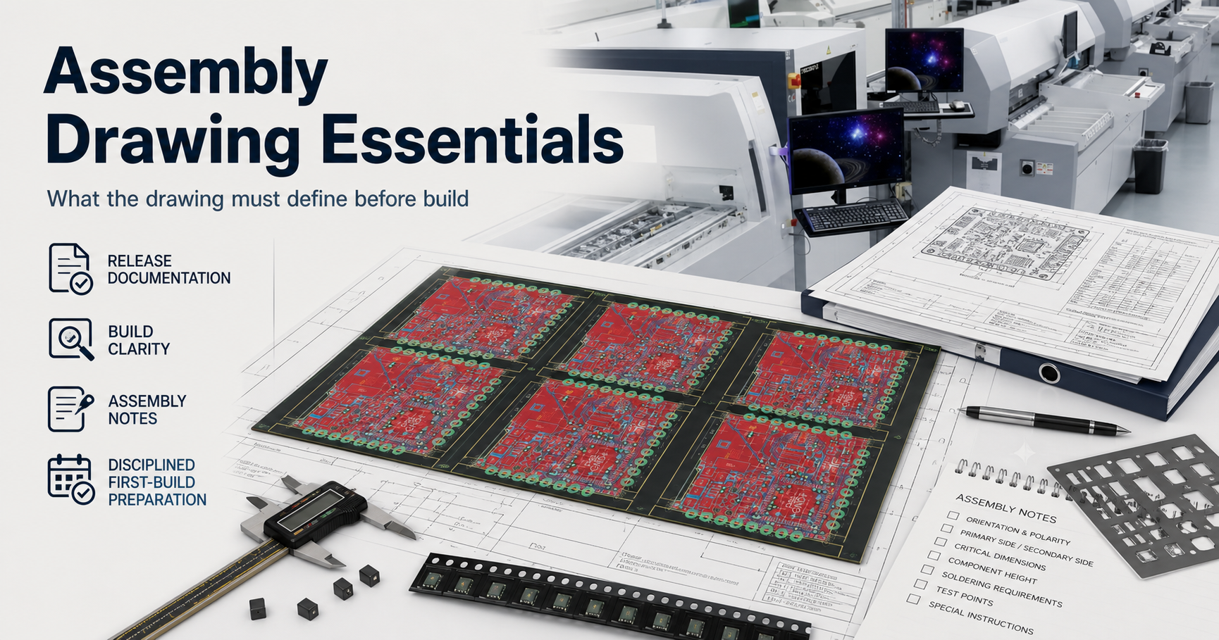
- An assembly drawing should be treated as a build-interpretation document, not as optional artwork around the BOM.
- The most useful boundary is to separate component identity, placement intent, polarity visibility, process routing notes, and release revision control.
- A board can have valid Gerbers and a workable BOM and still stall if the assembly drawing leaves orientation, side, variant, or special-handling intent unclear.
- The safest explanation is to show what the drawing must define before first build and what still belongs to other package artifacts.
Quick Answer Assembly drawing essentials start with one question: can the build team understand the intended population and placement behavior without guessing? A useful drawing makes polarity, side, reference visibility, special process notes, and variant boundaries explicit. It does not replace the BOM, centroid file, or test plan, but it keeps those artifacts from being interpreted inconsistently during NPI and release review.
For the broader quality-stack view that connects assembly input control, inspection layers, and release gates, start with the PCBA Assembly Test and Quality Guide.
Table of Contents
- What should engineers review first?
- What counts as an assembly drawing here?
- Which drawing elements matter most before first build?
- How should the drawing stay aligned with BOM, placement data, and test planning?
- What should be frozen before RFQ, first build, or release?
- Next steps with APTPCB
- FAQ
- Public references
- Author and review information
What should engineers review first?
Start with polarity visibility, population clarity, process notes, reference alignment, and revision ownership.
That order matters because the drawing often becomes the human-readable bridge between design intent and factory interpretation. If it is weak, the first build slows down under engineering queries that should have been resolved before setup.
The first engineering questions are usually:
- Can the operator or reviewer identify orientation-sensitive parts without guessing?
- Does the drawing show which components are installed, omitted, or variant-controlled?
- Are special assembly routes such as mixed SMT and THT, selective solder, hand-insert, or keep-out handling visible enough?
- Do the drawing references align with the BOM and placement data?
- Does the released drawing clearly belong to the same revision state as the rest of the package?
| Review boundary | What it answers | What it does not prove |
|---|---|---|
| Polarity visibility | Whether orientation-sensitive parts are interpretable during setup and review | That the underlying footprint library is correct by itself |
| Population clarity | Whether installed versus uninstalled content is visible to the build team | That sourcing or alternate approval is complete |
| Process notes | Whether special routing or handling intent is exposed | That inspection or test coverage is already defined |
| Reference alignment | Whether reviewers can cross-check the drawing against BOM and placement data | That machine coordinates are correct by default |
| Revision ownership | Whether the drawing belongs to the current release package | That first-build validation has already passed |
What counts as an assembly drawing here?
Here, assembly drawing essentials means the document layer that explains how the intended build should be interpreted during PCBA setup, review, and first-build confirmation.
That usually includes:
- visible component locations and reference context
- polarity and pin-1 visibility where needed
- side or population context for top, bottom, or mixed-process handling
- special notes for hand-insert, selective solder, coating, labeling, or other process-sensitive branches
- variant or DNP visibility where the drawing needs to support build interpretation
- revision control that matches the released package
It does not mean:
- the drawing alone defines the component set
- the drawing replaces pick-and-place coordinates
- the drawing replaces electrical-test planning
- the drawing alone closes shipment release
That boundary matters because many assembly problems appear when teams ask the drawing to compensate for missing BOM control or missing placement data. The better rule is simpler:
the assembly drawing should make build intent readable, while the rest of the package still owns sourcing, machine data, and test evidence.
Which drawing elements matter most before first build?
The most important drawing elements are the ones that prevent interpretation drift.
1. Polarity and orientation visibility
The drawing should help reviewers confirm orientation-sensitive content such as:
- pin-1-sensitive packages
- polarized passives
- diodes and LEDs
- connectors or keyed mechanical parts
The main purpose is not decorative completeness. It is to reduce ambiguity during setup, FAI, and later troubleshooting.
A common polarity trap starts when the PCB silkscreen is too cramped to stay readable, or uses a diode or cathode symbol that is not clear enough under real factory conditions. The risk becomes much worse when the BOM introduces an approved alternate part because of shortage, and the alternate package marks polarity in a different way from the original component family. One part may use a cathode stripe, another may use a molded notch or bar that does not visually agree with the board silkscreen. If the assembly drawing does not lock the intended orientation as the source of truth, setup operators and FAI reviewers fall back to the silkscreen by habit. The result is not one reversed diode or tantalum capacitor. The same wrong assumption gets repeated across the lot, and all polarity-sensitive parts are installed backwards.
That failure is expensive precisely because it looks simple. Static review may not stop it, and once 500 boards have passed reflow and then moved into underfill or coating, the rework burden can exceed the board value itself. At that stage the problem is no longer a drawing preference. It is a release-package failure: the silkscreen was never reliable enough to carry polarity truth after the BOM changed.
For a dedicated orientation guide, see SMT Component Polarity.
2. Population and variant clarity
A useful drawing makes it easier to understand which components belong to the released build and which are intentionally omitted.
That matters most when:
- the board has DNP or DNI lines
- multiple variants share one base design
- optional connectors or programmed parts change by customer or revision
3. Mixed-process and special-handling notes
The drawing should expose process-sensitive branches that the BOM alone may not communicate clearly.
Examples include:
- mixed SMT and THT populations
- selective-solder or hand-solder exceptions
- install-after-reflow instructions
- areas affected by coating, masking, or later integration work
For process-route context, see Mixed Assembly Planning.
4. Reference consistency with other files
The drawing is most useful when the reference language matches the BOM and placement package cleanly. If one artifact uses a different naming or grouping pattern, review slows down immediately.
| Drawing element | Why it matters | What can go wrong if it stays vague |
|---|---|---|
| Polarity callouts | Protects orientation-sensitive population from interpretation drift | Reversed or disputed placement intent |
| Variant visibility | Keeps the released population understandable | Wrong parts loaded or omitted |
| Process notes | Exposes handling that is not obvious from the BOM alone | Setup questions during NPI or mixed-process routing |
| Reference consistency | Supports cross-checking against BOM and placement data | Reviewers lose one-to-one traceability between files |
| Revision block | Connects the drawing to the actual release state | Old instructions travel with a newer build package |
A common factory-floor failure chain starts when the drawing leaves polarity, Pin 1, variant, or install-after-reflow intent implied rather than explicit. The BOM may still look clean, the placement file may still import, and setup can move forward under one quiet assumption about connector orientation or optional population. If that assumption is not stopped during first-build review, the machine program and operator notes repeat it across the lot. The problem is then discovered late through AOI, debug, or customer-facing build review, turning one weak drawing note into batch rework and release delay.
How should the drawing stay aligned with BOM, placement data, and test planning?
The drawing should stay aligned with the rest of the assembly package without absorbing their responsibilities.
| Package artifact | What it mainly owns | What it should not be confused with |
|---|---|---|
| BOM | Component identity, alternates, DNP status, sourcing posture | Human-readable placement interpretation |
| Assembly drawing | Placement and build-interpretation clarity | The full sourcing or electrical-test definition |
| Placement data | Machine-readable coordinate and rotation input | Variant ownership or special note visibility |
| Test plan | Electrical or functional verification intent | Placement-definition authority |
This separation matters because file completeness is not the same thing as file duplication.
The safer release sequence is:
- clean the BOM so the intended population is controlled
- clean the assembly drawing so orientation and process notes are readable
- confirm the placement data matches the same revision state
- confirm FAI, inspection, and test expectations are defined at the package level
Useful companion pages:
- Assembly BOM Best Practices
- Testing & Quality
- First Article Inspection
- PCBA Assembly Test and Quality Guide
What should be frozen before RFQ, first build, or release?
Before serious RFQ, first build, or release, freeze:
- the drawing revision that matches the released BOM and placement package
- polarity, pin-1, and orientation visibility for all sensitive parts
- variant and DNP visibility where the drawing participates in population interpretation
- special process notes for mixed-process, hand-insert, or later handling branches
- the boundary between what the drawing owns and what still belongs to BOM, placement, and test documentation
If those items are still moving, the drawing may still be useful for discussion, but it is not yet strong enough to behave like a release-ready assembly definition layer.
Next steps with APTPCB
If your build package is already carrying variant complexity, approved alternate parts, or polarity-sensitive devices that cannot survive interpretation drift, do not wait for FAI to expose the gap on the factory floor. The same applies if first build keeps stalling because the drawing, BOM, centroid, and population notes still leave operators or reviewers asking which orientation is the real one.
Send the Gerber, BOM, centroid file, and the assembly drawing under review to sales@aptpcb.com, or upload the package through the quote page. APTPCB's PCBA release-package audit team will return an Assembly Interpretation & Polarity Conflict Review within 24 hours.
That review is designed to catch the failure before expensive first build: silkscreen blind spots, alternate-part polarity conflicts, variant boundary drift, and document gaps that force FAI into stop-and-wait mode. The goal is to lock one unambiguous manufacturing truth source before reflow, underfill, coating, and batch rework turn a readable drawing mistake into a release-cost problem.
If you need to go deeper before release, review:
FAQ
Can the assembly drawing replace the BOM?
No. The drawing supports build interpretation. The BOM still owns component identity, alternate governance, and population control.
What is the most important item to make visible in the drawing?
Usually polarity and orientation-sensitive content, because that is where first-build interpretation drift causes the fastest and most expensive confusion.
Should DNP or variant information appear in the drawing?
Sometimes yes. If the drawing is part of the build-interpretation package, it should make population differences readable enough to prevent loading mistakes.
Why does revision alignment matter so much?
Because a clean drawing attached to the wrong BOM or placement revision can still drive the wrong build behavior.
What is the most common mistake in assembly-drawing preparation?
Treating the drawing as a formality instead of as the document that keeps polarity, process notes, and build interpretation readable during NPI and release review.
Public references
APTPCB First Article Inspection Supports first-run verification and release-gate use for setup and documentation readiness.
APTPCB Testing & Quality Supports the broader quality path in which assembly-definition clarity stays separate from inspection and electrical-test ownership.
SMT Component Polarity Supports qualitative polarity-governance wording such as pin-1 visibility, zero-orientation discipline, and inspection posture.
Assembly BOM Best Practices Supports the component-definition layer that must stay aligned with the drawing.
PCBA Assembly Test and Quality Guide Supports the layered release-readiness framing around assembly inputs, inspection, test, and release gates.
Author and review information
- Author: APTPCB PCBA release-package content team
- Technical review: Assembly documentation, polarity, and NPI review team
- Last updated: 2026-05-13